Insulator ------ Bugs?
by Larry Larned
Reprinted from "INSULATORS - Crown Jewels of the Wire", December 1977, page 13
The transcontinental telephone toll line was constructed by American
Telephone & Telegraph Company in 1915. The line was constructed from New
York to San Francisco and routed through Trenton, Pittsburgh, Chicago, Des
Moines, Omaha, Denver, Cheyenne, Salt Lake City, and Sacramento.
Open wire type
construction was utilized with No. 8 B. W. gauge copper .165 inches in diameter.
There were 130,000 poles used in the line, many of them carrying no wires except
the four wires making up the three transcontinental circuits spanning a distance
of 3,400 miles. The line consisted of two physical circuits and one phantom
circuit.
Prior to 1915 a toll line 3,400 miles long was not possible without
technological improvements in telephone engineering. In the words of ATT's
President, Theodore N. Vail, "It is the cumulative effect of improvements,
great and small, in telephone, transmitter, line cable, switchboard, and every
other piece of apparatus or plant required in the transmission of speech"
that made the long distance service possible.
One of the improvements which Mr.
Vail referred to was the development of the loading coil. It was found that the
efficiency of long telephone circuits could be increased by inserting inductance
coils in the circuit at suitable distances. The coils consisted of a core,
shaped like a ring, made up of very fine, carefully insulated, iron wires .004
of an inch in diameter. Around this iron core are wound two copper wires, one
for each side of the telephone circuit. These windings of copper wire are so
placed that when in service each will magnetize the core in the same direction,
so the mutual induction will be added to the self induction. The coils were
placed in suitable iron cases and mounted on the cross arms along the line.
However, it was soon found that the problem of loading No. 8 circuits was
largely one of insulation. Low insulation on a loaded circuit has a much greater
effect upon the efficiency of the circuit than has low insulation on an unloaded
circuit. As the efficiency of the circuit is increased, the more serious becomes
the insulation problem. The loading coils were connected to the open wire
circuits with rubber-covered bridle wire. The leakage over the braid of the
bridle wire turned out to be a serious problem; and to solve it, special
insulators, called bridle insulators, through which the bridle wire passed, were developed. (See pages 20 - 21 of February 1977
Crown Jewels.) The bridle insulator, however, did not completely solve the problem of
insulation on the loaded circuits. Each circuit on the transcontinental line
employed more than 250,000 pin type insulators, and considering the leakage at
each insulator during wet weather, it was evident that the cumulative effect of
any improvement in the insulation at each insulator would be of great help.
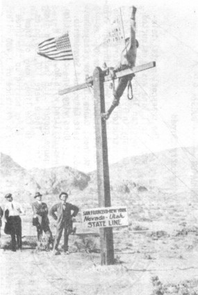
Final pole of the Transcontinental Line.
(Courtesy AT&T)
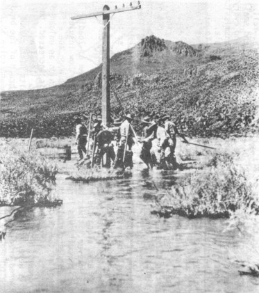
Construction of the Transcontinental Line through Nevada 1914.
(Courtesy AT&T)
Therefore, a new type of double petticoated porcelain insulator was designed and
placed on the line. However, it was not too long after the line was placed in
service, that strange events took place which puzzled engineers and defied the
laws of electrical science and the conclusion of laboratory experiments. The
porcelain insulators became infested with bugs - what species of bug I don't
know, and Bell System officials won't divulge. However, the opacity of the
porcelain and the shelter provided by the double petticoat skirt caused the bugs
to home in on the line and to propagate more bugs. The Bell System, not wishing
to employ the people necessary to station a flit gunner at each pole, decided to
remove all of the porcelain insulators and replace them with glass insulators.
During 1918 the job was accomplished, the bugs lost their home, and once again
the technology of man prevailed.
An interesting question concerning the
transcontinental line is, what type of porcelain insulator was developed, and
what type of glass insulator replaced it. AT&T has found no record for the
development and purchase of 500,000 porcelain insulators, nor the purchase of
500,000 glass replacements. I can speculate, however, with the assistance of
Jack Tod, that the porcelain was most probably U-177. Three photographs of the
line strongly suggest U-177. This insulator was made by Locke and cataloged for
general distribution in 1916 as #3188. Its replacement was, in all probability,
CD 152, the style in general use during this era for communications work. Of
course as time, went on, the CD 154 was developed with its larger capacity wire
groove. The CD 154 was first produced in 1922 and became the standard long
distance insulator for the Bell System.
Perhaps some of CJ's readers who live
near the original route of the line and have found relics from it, could describe their goodies and verify the legacy which
photographs appear to describe.
|

)
)
)